
In contemporary manufacturing, architecture, and transportation design, controlling how acoustic energy interacts with structural matter is a foundational engineering metric. Unchecked noise, vibration, and harshness (NVH) cause structural fatigue, lower consumer product quality, and contribute to chronic environmental health risks. Designing acoustic environments or high-performance noise-reduction metrics requires a rigorous approach called acoustic material characterization.
Acoustic material characterization is the experimental and analytical process of determining the physical, macrostructural, and wave-propagating properties of a material. This guide explores the fundamental parameters, measurement frameworks, analytical models, and industry standards that define this discipline.
1. Fundamentals of Wave-Matter Interaction
When an airborne or structure-borne acoustic wave encounters a material boundary, it undergoes energy transformation. Understanding this breakdown is critical before selecting testing systems or processing algorithms.
                    Incident Wave (Ei)
                 ─────────────────────────►
                             │
                             ├──► Reflected Wave (Er)
                             │
                      ┌──────┴──────┐
                      │  Acoustic   │
                      │  Material   │ ──► Dissipated/Absorbed Wave (Ea)
                      └──────┬──────┘
                             │
                             └──► Transmitted Wave (Et)
The conservation of energy dictates that the total incident energy (\(E_{i}\)) equals the sum of the reflected (\(E_{r}\)), absorbed (\(E_{a}\)), and transmitted (\(E_{t}\)) energies:
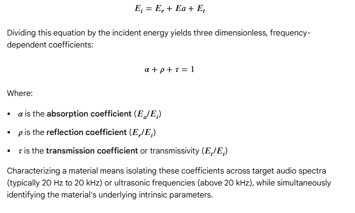
2. Intrinsic vs. Extrinsic Material Parameters
Acoustic engineers classify descriptors into two distinct categories:
Extrinsic Parameters (Performance Metric Level)
Extrinsic properties depend heavily on the material’s dimensions, mounting configurations, and boundary conditions. These include:
- Sound Absorption Coefficient (\(\alpha \)): The ratio of non-reflected sound energy to incident sound energy.
- Transmission Loss (TL): Expressed in decibels (dB), this measures a material’s internal resistance to letting sound pass through it.
- Surface Acoustic Impedance (\(Z_{s}\)): The complex ratio of acoustic pressure to particle velocity at the material’s face.
Intrinsic Parameters (Macrostructural Level)
Intrinsic parameters belong purely to the material’s structural matrix, independent of thickness or configuration. These values drive predictive models:
- Open Porosity (\(\phi \)): The volume fraction of interconnected pore space to the total material volume.
- Static Airflow Resistivity (\(\sigma \)): The resistance per unit thickness that a material matrix exerts against steady air flowing through it (measured in \(\text{Pa}\cdot\text{s}/\text{m}^2\)).
- Tortuosity (\(\alpha _{\infty }\)): A geometric index reflecting the complexity and curvature of the inner pore pathways relative to a straight path.
- Viscous and Thermal Characteristic Lengths (\(\Lambda, \Lambda’\)): Metrics that govern high-frequency energy dissipation caused by friction and heat transfer at the pore walls.
3. Core Measurement Methodologies
Accurate characterization requires isolating specific sound field types. Engineers rely on three main experimental methodologies.
3.1 Impedance Tube Methods (Normal Incidence)
The impedance tube (or Kundt tube) is the most widely accessible instrument for characterizing small material samples under normal sound incidence (\(0^{\circ }\) perpendicular waves).
┌──────────┐     Microphone 1  Microphone 2     ┌──────────────┐
│          │       ┌───┐          ┌───┐         │ █▄█▄█▄█▄█▄█  │
│  Source  │───────│ P1│──────────│ P2│─────────│  Material    │
│ (Speaker)│       └───┘          └───┘         │ █▄█▄█▄█▄█▄█  │
└──────────┘                                    └──────────────┘
 ◄────────────────────── Tube Length ─────────────────────────►
The Two-Microphone Transfer Function Method (ISO 10534-2 / ASTM E1050)
A loudspeaker generates broadband, pseudo-random noise at one end of a rigid, smooth-walled tube. The sound propagates as plane waves down the tube, strikes the material specimen, and reflects. Two flush-mounted microphones monitor the combined sound pressure field.
By calculating the complex acoustic transfer function (\(H_{12}\)) between microphone position 1 and 2, the system splits the wave field into its incident and reflected components:
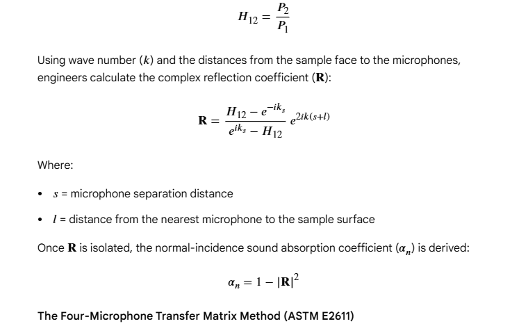
3.2 Reverberation Room Testing (Random/Diffuse Incidence)
In contrast to the normal-incidence tube method, real-world deployments (such as architectural acoustics) subject materials to waves arriving from all angles simultaneously. Diffuse field characterization relies on a large, structurally isolated reverberation room.
Theoretical Basis: Sabine’s Equation
The test involves measuring the room’s reverberation time (\(T_{60}\))—the time required for the sound pressure level to decay by 60 decibels after the sound source stops.
Testing requires two steps: first measuring the empty room, and then measuring the room with a large specimen layout (typically 10 to 12 square metres) on the floor or walls. According to Sabine’s formula, the room’s total equivalent absorption area (\(A\)) is:
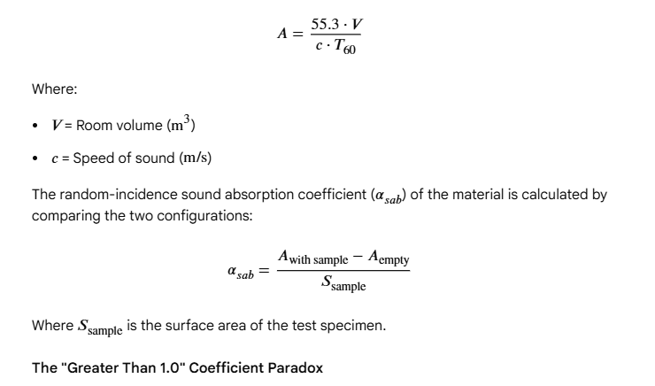
The “Greater Than 1.0” Coefficient Paradox
A known quirk of ASTM C423 and ISO 354 reverberation room testing is that highly absorptive materials often return values above \(1.0\) (e.g., \(\alpha = 1.15\)). This physical impossibility stems from diffraction effects at the edges of the sample patch, which make the sample look acoustically larger than its physical dimensions.
3.3 Free-Field and In-Situ Techniques
When materials cannot be cut into circular tube plugs or scaled up to large panels, engineers use non-destructive, in-situ free-field systems.
- Microphone-Hydrophone / PU-Probes: These utilize closely paired pressure (\(P\)) and particle velocity (\(U\)) sensors. By directly measuring local impedance (\(Z = P/U\)) near a boundary, engineers can map material absorption profiles on-site (e.g., inside aircraft cabins or historical buildings).
- Spatial Fourier Transform (SFT) Arrays: Multi-microphone arrays capture the complex sound field reflection mapping across various incidence angles, unlocking deep material matrices without a dedicated lab.
4. Analytical and Microstructural Modeling
To design new noise-control treatments, researchers use predictive modeling rather than relying solely on trial-and-error physical tests.
4.1 The Biot-Allard Poroelastic Wave Equation
The most robust framework for acoustic materials is the Biot-Allard theory. It models porous matter as two co-existing, interacting phases: an elastic solid skeletal frame and a viscous fluid phase filling the pores.
Three waves propagate simultaneously through a Biot medium:
- A fast longitudinal wave (compressional wave where frame and fluid move in-phase).
- A slow longitudinal wave (compressional wave where frame and fluid move out-of-phase, rapidly dissipating energy via fluid friction).
- A transverse shear wave.
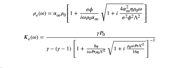
4.2 Rigid-Frame Simplifications: The Johnson-Champoux-Allard (JCA) Model
If the material’s solid skeleton is stiff enough to resist vibration under acoustic pressures, it can be modeled as a rigid frame. The JCA Model defines the effective density (\(\rho _{e}\)) and bulk modulus (\(K_{e}\)) of the interstitial air using the five intrinsic macrostructural parameters mentioned in Section 2:
7.2 Sustainable and Bio-Based Absorbers
Environmental regulations are driving a shift toward bio-based acoustic absorbers. Materials like agricultural hemp fiber, mycelium matrices, recycled textiles, and cellular wood composites are replacing energy-intensive mineral wool and petroleum foams. Characterizing these natural media requires accounting for structural inconsistencies, moisture absorption, and cellular irregularity over time.
Summary
Acoustic material characterization bridges raw material science and environmental sound design. Whether using an impedance tube for rapid laboratory benchmarking or a reverberation chamber for real-world validation, understanding these testing methodologies, analytical frameworks, and international standards ensures that materials perform as intended in the field.